TECHNICAL
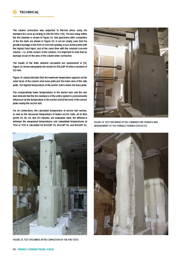
FIGURE 24: TEST SPECIMENS IN THE COMBINED FIRE FURNACE AND
ARRANGEMENT OF THE FURNACE THERMOCOUPLES 12
The column connection was subjected to thermal stress using the
standard fire curve according to DIN EN 1363-1 16. The test setup within
the fire chamber is shown in Figure 24. Test specimens after completion
of the fire tests are shown in Figure 25. It can be clearly seen that the
greatest damage in the form of concrete spalling occurs at the points with
the highest heat input, and at the same time with the smallest concrete
volume – i.e. at the corners of the columns. It is important to note that no
damage occurs in the area of the column shoe connection.
The results of the finite element calculation are summarized in 13.
Figure 26 shows exemplarily the results for BOLDA® 39 after a duration of
120 min.
Figure 26 clearly indicates that the maximum temperature appears on the
outer faces of the column shoe base plate and the lower area of the side
plate. The highest temperature of the anchor bolt is inside the base plate.
The comparatively lower temperatures in the anchor bars and the rear
bars indicate that the fire resistance of the entire system is predominantly
influenced by the temperature in the anchor bolt at the level of the anchor
plate nearby the anchor bolt.
For all connections, the calculated temperature of anchor bolt section,
as well as the measured temperature of tested anchor bolts, all at time
points 30, 60, 90, and 120 minutes, are evaluated. Next, the difference
between the measured temperatures and calculated temperatures at
TE14 or TE15 is calculated for BOLDA® 30, BOLDA® 39, and BOLDA® 52.
FIGURE 25: TEST SPECIMENS AFTER COMPLETION OF THE FIRE TESTS
60 PEIKKO CONNECTIONS 1/2021