SHEAR RESISTANCE
Two shear resistance tests using BOLDA® 30 and BOLDA® 52 have
been carried out. The results are given in Table 4. The measured shear
resistances Vu,test have been converted to Ve,i taking into account the
ratio of nominal to actual steel strength (fu/fu,test). The values obtained are
compared to the theoretical value Vt,i.
The comparison in Table 3 clearly shows that the requirement Ve,i/Vt,i ≥
1.0 is clearly fulfilled. Therefore, a value ks = 1.0 can be used in the shear
design according to EN 1992-1-1.
In the following, all characteristic values are listed.
Column shoe BOLDA®
30
BOLDA®
36
BOLDA®
39
BOLDA®
45
BOLDA®
52
Steel failure
Resistance NkN 299 436 521 697 938
Rd,s Bending
ɳ- 1.0
d resistance
factor
Bending
stiffness
factor
kL - 1.0
Shear
resistance
factor
ks - 1.0
ADDITIONAL INVESTIGATIONS OF THE DEFLECTION BEHAVIOR WITH
FE ANALYSIS
To further evaluate the load bearing behavior of column shoe connections
in comparison to cast-in-situ columns, a small research project using finite
element analysis of both systems has been conducted in collaboration
with University of Stuttgart 18. Two systems applying BOLDA® 30 and
BOLDA® 52 column shoe connections have been investigated, as well
as the associated cast-in-situ (monolithic) models. The test setup for the
bending stiffness, tests acc. to Figure 9 b) including the measuring points
according to the previous section have been adopted for both column
shoe connections as well as monolithic cast-in-situ systems. Within the
analysis, the following material properties for the different components
have been used (Table 4).
The non-linear finite element program ATENA® can simulate the
real structural behavior including concrete cracking, crushing and
reinforcement yielding. The software has been extensively validated on
experimental data and international round robin prediction analysis.
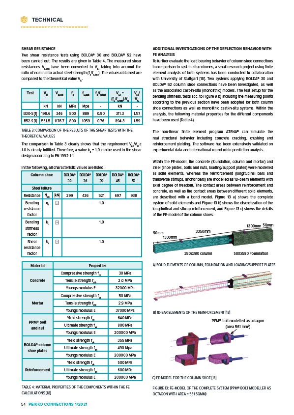
Within the FE-model, the concrete (foundation, column and mortar) and
steel (shoe plates, bolts and nuts, loading/support plates) were modelled
as solid elements, whereas the reinforcement (longitudinal bars and
transverse stirrups, anchor bars) are modelled as 1D-beam elements with
axial degree of freedom. The contact areas between reinforcement and
concrete, as well as the contact areas between different solid elements,
are described with a bond model. Figure 13 a) shows the complete
system of solid elements and Figure 13 b) shows the discretization of the
longitudinal and stirrup reinforcement, and Figure 13 c) shows the details
of the FE-model of the column shoes.
380x380 column 580x580 Foundation
50mm
A) SOLID ELEMENTS OF COLUMN, FOUNDATION AND LOADING/SUPPORT PLATES
B) 1D-BAR ELEMENTS OF THE REINFORCEMENT 18
50mm
1300mm
3350mm
1300mm
PPM® bolt modelled as octagon
(area 561 mm2)
FIGURE 13: FE-MODEL OF THE COMPLETE SYSTEM (PPM® BOLT MODELLER AS
OCTAGON WITH AREA = 561 SQMM)
Test Vt,i Vu,test fu fu,test fu/fu,test Ve,i =
(fu/fu,test)·Vu
Ve,i/
Vt,i
kN kN MPa Mpa - kN -
B30-S 1 198.6 346 800 889 0.90 311.3 1.57
B52-S 1 561.5 1176.7 800 1059 0.76 894.3 1.59
TABLE 3: COMPARISON OF THE RESULTS OF THE SHEAR TESTS WITH THE
THEORETICAL VALUES
Material Properties
Concrete
Compressive strength fck 30 MPa
Tensile strength fctk 2.0 MPa
Youngs modulus E 32000 MPa
Mortar
Compressive strength fck 50 MPa
Tensile strength fctk 2.9 MPa
Youngs modulus E 37000 MPa
PPM® bolt
and nut
Yield strength fyk 640 MPa
Ultimate strength fuk 800 MPa
Youngs modulus E 200000 MPa
BOLDA® column
shoe plates
Yield strength fyk 355 MPa
Ultimate strength fuk 490 Mpa
Youngs modulus E 200000 MPa
Reinforcement
Yield strength fyk 500 MPa
Ultimate strength fuk 600 MPa
Youngs modulus E 200000 MPa
TABLE 4: MATERIAL PROPERTIES OF THE COMPONENTS WITHIN THE FE
CALCULATIONS 18
C) FE-MODEL FOR THE COLUMN SHOE 18
TECHNICAL
54 PEIKKO CONNECTIONS 1/2021