BENDING STIFFNESS
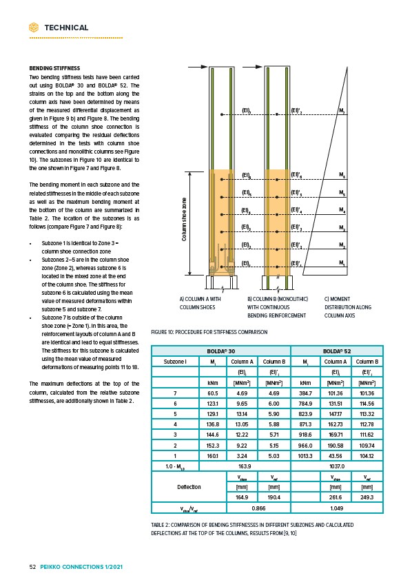
Two bending stiffness tests have been carried
out using BOLDA® 30 and BOLDA® 52. The
strains on the top and the bottom along the
column axis have been determined by means
of the measured differential displacement as
given in Figure 9 b) and Figure 8. The bending
stiffness of the column shoe connection is
evaluated comparing the residual deflections
determined in the tests with column shoe
connections and monolithic columns see Figure
10). The subzones in Figure 10 are identical to
the one shown in Figure 7 and Figure 8.
The bending moment in each subzone and the
related stiffnesses in the middle of each subzone
as well as the maximum bending moment at
the bottom of the column are summarized in
Table 2. The location of the subzones is as
follows (compare Figure 7 and Figure 8):
• Subzone 1 is identical to Zone 3 =
zone
shoe Column column shoe connection zone
• Subzones 2–5 are in the column shoe
zone (Zone 2), whereas subzone 6 is
located in the mixed zone at the end
of the column shoe. The stiffness for
subzone 6 is calculated using the mean
value of measured deformations within
subzone 5 and subzone 7.
• Subzone 7 is outside of the column
shoe zone (= Zone 1). In this area, the
reinforcement layouts of column A and B
are identical and lead to equal stiffnesses.
The stiffness for this subzone is calculated
using the mean value of measured
deformations of measuring points 11 to 18.
The maximum deflections at the top of the
column, calculated from the relative subzone
stiffnesses, are additionally shown in Table 2. M7
(EI)7 (EI)’7
(EI)6 M6
M5
M4
M3
M2
M1
(EI)’6
(EI)5 (EI)’5
(EI)4 (EI)’4
(EI)3 (EI)’3
(EI)2 (EI)’2
(EI)1 (EI)’1
A) COLUMN A WITH
COLUMN SHOES
B) COLUMN B (MONOLITHIC)
WITH CONTINUOUS
BENDING REINFORCEMENT
FIGURE 10: PROCEDURE FOR STIFFNESS COMPARISON
C) MOMENT
DISTRIBUTION ALONG
COLUMN AXIS
BOLDA® 30 BOLDA® 52
Subzone i Mi Column A Column B Mi Column A Column B
(EI)i (EI)’i (EI)i (EI)’i
kNm MNm2 MNm2 kNm MNm2 MNm2
7 60.5 4.69 4.69 384.7 101.36 101.36
6 123.1 9.65 6.00 784.9 131.51 114.56
5 129.1 13.14 5.90 823.9 147.17 113.32
4 136.8 13.05 5.88 871.3 162.73 112.78
3 144.6 12.22 5.71 918.6 169.71 111.62
2 152.3 9.22 5.15 966.0 190.58 109.74
1 160.1 3.24 5.03 1013.3 43.56 104.12
1.0 · Mt,0 163.9 1037.0
Deflection
vshoe vref vshoe vref
mm mm mm mm
164.9 190.4 261.6 249.3
vshoe/vref 0.866 1.049
TABLE 2: COMPARISON OF BENDING STIFFNESSES IN DIFFERENT SUBZONES AND CALCULATED
DEFLECTIONS AT THE TOP OF THE COLUMNS, RESULTS FROM 9, 10
TECHNICAL
52 PEIKKO CONNECTIONS 1/2021