TEST SERIES
INTRODUCTION
The scope of the test series was to broaden
the knowledge regarding the load transfer
behavior of a composite column in the vicinity
of the load introduction. The main principles
are available from the standards and from
the literature, but design of an advanced joint
requires assumptions which are critical to
overall behavior. These tests were to examine
those assumptions.
Where the preliminary tests concentrated on the
principals of the shear transfer, the later tests
with the corbels were to provide information
about the behavior of a specific joint type. The
specimens and the loading setup were planned
so that they would represent a composite
section taken out from a typical continuous
multi story column.
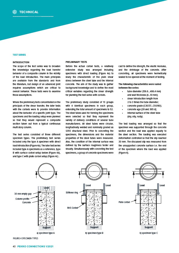
The test series consisted of three different
specimen types. The preliminary test series
included only the type A specimen with direct
load introduction (Figure 4a). The later test series
included type A specimens as a reference, type
B with surface corbel setup below (Figure 4b),
and type C with plate corbel setup (Figure 4c) .
PRELIMINARY TESTS
Before the actual corbel tests, a relatively
extensive study was arranged including
specimens with direct loading (Figure 4a) to
study the characteristic of the plain shear
stress between the steel tube and the internal
concrete. The aim of the study was to gather
background knowledge and to define the most
critical variables regarding the shear strength
for planning the test series with corbels.
The preliminary study consisted of 13 groups
with 4 identical specimens in each group,
extending the total amount of specimens to 52.
The steel tubes used for forming the specimens
were selected so that they represent the
variety of delivery conditions of several tube
manufacturers. All steel tubes were circular,
longitudinally welded and nominally graded as
S355 structural steel. Prior to concreting the
specimens, the dimensions and the material
properties of the steel tubes were measured.
Also, the condition of the internal surface was
defined by the surface roughness tester and
visually. Simultaneously with concreting the test
specimens, a group of concrete specimens were
cast to define the strength, the elastic modulus,
and the shrinkage of the concrete. After
concreting, all specimens were hermetically
sealed to be opened at the moment of testing.
The following characteristics were varied
between the series:
• tube diameter (139.6…406.4 mm)
and wall thickness (4…10 mm);
• shear introduction length from
2 to 3 times the tube diameter;
• concrete grade (C30/37…C50/60);
• concrete age (28 and 365 d);
• internal surface of the steel tube
(dry, oily, rusty).
The test loading was arranged so that the
specimen was supported through the concrete
section and the load was applied equally to
the steel section. The loading was executed
deformation controlled so that the slip reached
30 mm. The discussed slip was measured from
the unsupported concrete surface i.e. the end
of the specimen where the load was applied
(Figure 4).
a) specimen type A
30 mm empty gap
Column profile
FIGURE 4 SPECIMEN TYPES
Plate corbel
RHS Corbel
Load Load Load Load
b) specimen type B b) specimen type C
Concrete
Stiffener ring
Load
Support Support Support
TECHNICAL
40 PEIKKO CONNECTIONS 1/2021