TECHNICAL
LOAD BEARING TESTS
In the load bearing shear tests, the columns were bolted to massive
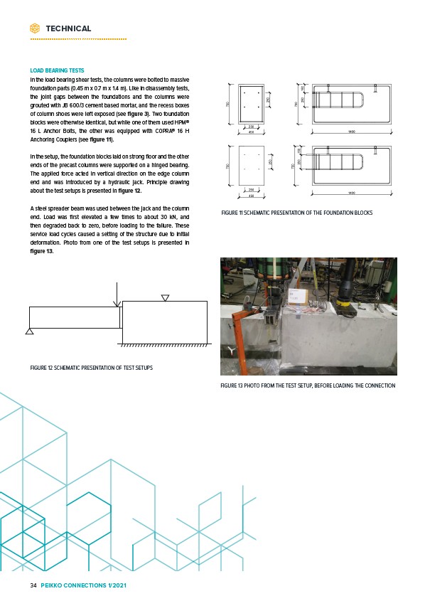
foundation parts (0.45 m x 0.7 m x 1.4 m). Like in disassembly tests,
the joint gaps between the foundations and the columns were
grouted with JB 600/3 cement based mortar, and the recess boxes
of column shoes were left exposed (see figure 3). Two foundation
blocks were otherwise identical, but while one of them used HPM®
16 L Anchor Bolts, the other was equipped with COPRA® 16 H
Anchoring Couplers (see figure 11).
In the setup, the foundation blocks laid on strong floor and the other
ends of the precast columns were supported on a hinged bearing.
The applied force acted in vertical direction on the edge column
end and was introduced by a hydraulic jack. Principle drawing
about the test setups is presented in figure 12.
A steel spreader beam was used between the jack and the column
end. Load was first elevated a few times to about 30 kN, and
then degraded back to zero, before loading to the failure. These
service load cycles caused a setting of the structure due to initial
deformation. Photo from one of the test setups is presented in
figure 13.
FIGURE 11 SCHEMATIC PRESENTATION OF THE FOUNDATION BLOCKS
FIGURE 12 SCHEMATIC PRESENTATION OF TEST SETUPS
FIGURE 13 PHOTO FROM THE TEST SETUP, BEFORE LOADING THE CONNECTION
34 PEIKKO CONNECTIONS 1/2021