SUMMARY OF THE RESULTS
The size of the steel tube did not have an effect
to the achieved shear stress within the tested
tube range. Neither the material properties
of concrete of steel did not show any effect
to the shear stress levels. The shrinkage of
the hermetically stored concrete specimens
remained low (0.0076…0.0172%) and the
ageing of the concrete did not have an effect
to the achieved shear stresses or the effect of
small shrinkage might be compensated by the
also small increase in the concrete strength.
The shear introduction length did not have a
significant effect to the shear stresses and the
difference can be assumed to be caused by the
distributions of the longitudinal strains along the
steel tubes.
Even though there were quite a lot of variation in
the conditions of the internal surfaces especially
when inspected visually the roughness did not
show any significant effect to the shear stresses.
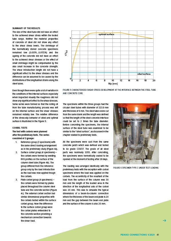
Some series were formed so that the rolling oil
from the tube manufacturing process was left
on the internal surface and the shear stresses
remained notably low. The relative difference
of the stress-slip behavior of oiled and optimal
surface is illustrated in the Figure 5.
CORBEL TESTS
The test with corbels were planned
after the preliminary tests. The series
consisted of 3 groups:
1. Reference group (3 specimens) with
the same direct loading arrangement
as in the preliminary study (Figure 4a).
2. Surface corbel group (4 specimens) –
the corbels were formed by welding
RHS profiles on the surface of the
column steel tube (Figure 4b). The
group differed from the reference
group only by the load introduction
as the load was now applied trough
the corbels.
3. Plate corbel group (4 specimens) –
the corbels were formed by plates
placed throughout the column steel
tube and the concrete section (Figure
4c). The external corbel section had
similar dimensional properties with
the corbels tested within the surface
corbel group. Now the difference
to the surface corbel group were
the corbel plates embedded to
the concrete section providing a
mechanical connection towards
the shear load.
1
0
optimal surface
0 2 4 6 8 10 12 14 16 18 20
τ/τRd
Slip mm
The specimens within the three groups had the
circular steel tubes with diameter of 323.9 mm
and thickness of 6 mm. The steel tubes were cut
from the same blank and the length was defined
so that the length of the steel concrete interface
could be set to 2 times the tube diameter.
Before concreting the specimens, the internal
surface of the steel tube was examined to be
similar to the “oiled surface”, as discussed in the
chapter related to preliminary tests.
All the specimens were cast from the same
concrete patch which was defined and tested
to be grade C30/37. The grade of all steel
parts was nominally S355. After concreting,
the specimens were hermetically sealed to be
opened at the moment of testing after 28 days.
The loading was arranged identically with the
preliminary tests with the exception with corbel
specimens where the load was applied on the
corbels. The eccentricity of the resultant of the
load from the surface of the column was 30
mm and the length of the loaded area in the
direction of the longitudinal axis of the corbel
was 20 mm. This was to simulate the typical
dimensions of a beam-to-column connection
where the thickness of the beam end plate is 20
mm and the gap between the beam end plate
and the surface of the column is also 20 mm.
oiled surface
FIGURE 5 CHARACTERIZED SHEAR STRESS DEVELOPMENT AT THE INTERFACE BETWEEN THE STEEL TUBE
AND CONCRETE CORE
FIGURE 6 SPECIMEN TYPE C UNDER TEST LOADING
PEIKKO CONNECTIONS 1/2021 41