2500
2000
1500
1000
500
0
0 1 2 3 4 5 6 7 8 9 10
Load kN
Deformation mm
Strain 1/10 000
deformation
strain
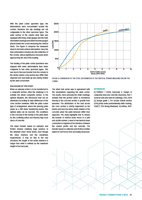
FIGURE 8 COMPARISON OF THE TOTAL DEFORMATION TO THE VERTICAL STRAINS MEASURED BELOW THE
CORBEL
With the plate corbel specimen type, the
deformations were concentrated around the
corbels, therefore the slip readings are not
comparable to the other specimen types. The
outer surface of the column steel tube was
equipped with linear strain gauges and the most
informative readings were taken from the gauges
placed below the corbel measuring the vertical
strain. The Figure 8 compares the measured
strain to the total vertical deformation. Here the
total deformation includes also the deflection of
the corbels, whose significance increases when
approaching the end of the loading.
The loading of the plate corbel specimens was
stopped with lower deformations than when
compared to two other specimen types. This
was due to the load transfer from the corbels to
the whole column cross section was stiffer than
expected and load build up was mainly limited
by the steel corbel itself.
DISCUSSION OF THE STUDY
When an external action is to be transferred to
a composite section, often the challenge is to
activate the whole composite section. In the
optimal situation, the introduced load can be
distributed according to axial stiffnesses of the
cross section members. With the plate corbel
type of arrangement, where the piercing plate
works as a stiff shear transferring device, this
optimal state can be reached. The conditions
in the concrete in the vicinity of the plate allow
for the confining action and thereby high local
stress of concrete.
The shear transfer based on adhesion and
friction showed relatively large variance in
the obtained shear stress levels, even though
the shear interface met the cleanliness
requirements. It may be that in the real
structures the length of the active interface is
longer than what is defined as the maximum
length in the Eurocode.
The latest test series was in agreement with
the assumptions regarding the plate corbel.
The results, more precisely the strain readings,
showed that the portion which is transferred
directly to the concrete section is greater than
assumed. The distribution of the load across
the cross section is strictly dependent on the
strains and here the stress strain relation of the
concrete under the plate behaved stiffer than
expected. The study highlights that to ensure
the transfer of vertical shear forces in a safe
and ductile manner, a level of mechanical shear
connection is required at the interface between
the column profile and the concrete. The
transfer based on adhesion and friction is better
suited for low forces from secondary structures.
REFERENCES
1 EN1994 1 1:2004, Eurocode 4: Design of
composite steel and concrete structures, Part 1:
General rules and rules for buildings, CEN, 2004
2 Design guide 1, For circular hollow section
(CHS) joints under predominantly static loading,
CIDECT, TÜV Verlag Rheinland, 1st edition, 1991
PEIKKO CONNECTIONS 1/2021 43