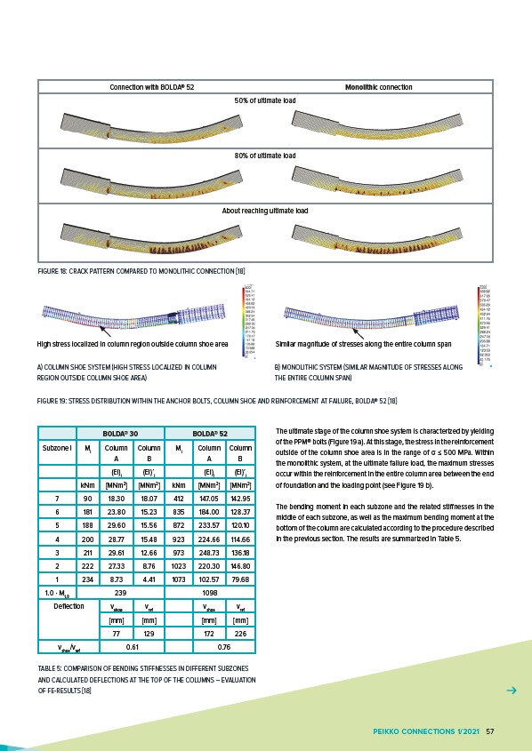
Connection with BOLDA® 52 Monolithic connection
50% of ultimate load
80% of ultimate load
About reaching ultimate load
FIGURE 18: CRACK PATTERN COMPARED TO MONOLITHIC CONNECTION 18
High stress localized in column region outside column shoe area Similar magnitude of stresses along the entire column span
B) MONOLITHIC SYSTEM (SIMILAR MAGNITUDE OF STRESSES ALONG
THE ENTIRE COLUMN SPAN)
A) COLUMN SHOE SYSTEM (HIGH STRESS LOCALIZED IN COLUMN
REGION OUTSIDE COLUMN SHOE AREA)
FIGURE 19: STRESS DISTRIBUTION WITHIN THE ANCHOR BOLTS, COLUMN SHOE AND REINFORCEMENT AT FAILURE, BOLDA® 52 18
The ultimate stage of the column shoe system is characterized by yielding
of the PPM® bolts (Figure 19 a). At this stage, the stress in the reinforcement
outside of the column shoe area is in the range of σ ≤ 500 MPa. Within
the monolithic system, at the ultimate failure load, the maximum stresses
occur within the reinforcement in the entire column area between the end
of foundation and the loading point (see Figure 19 b).
The bending moment in each subzone and the related stiffnesses in the
middle of each subzone, as well as the maximum bending moment at the
bottom of the column are calculated according to the procedure described
in the previous section. The results are summarized in Table 5.
BOLDA® 30 BOLDA® 52
Subzone i Mi Column
A
Column
B
Mi Column
A
Column
B
(EI)i (EI)’i (EI)i (EI)’i
kNm MNm2 MNm2 kNm MNm2 MNm2
7 90 18.30 18.07 412 147.05 142.95
6 181 23.80 15.23 835 184.00 128.37
5 188 29.60 15.56 872 233.57 120.10
4 200 28.77 15.48 923 224.66 114.66
3 211 29.61 12.66 973 248.73 136.18
2 222 27.33 8.76 1023 220.30 146.80
1 234 8.73 4.41 1073 102.57 79.68
1.0 · Mt,0 239 1098
Deflection vshoe vref vshoe vref
mm mm mm mm
77 129 172 226
vshoe/vref 0.61 0.76
TABLE 5: COMPARISON OF BENDING STIFFNESSES IN DIFFERENT SUBZONES
AND CALCULATED DEFLECTIONS AT THE TOP OF THE COLUMNS – EVALUATION
OF FE-RESULTS 18
PEIKKO CONNECTIONS 1/2021 57