Load kN - displacement mm
kN
400
350
300
250
200
150
100
50
0
Load kN - displacement mm
diagram
HPM® Anchor Bolt
COPRA® Anchoring Coupler
diagram
0 10 20 30
mm
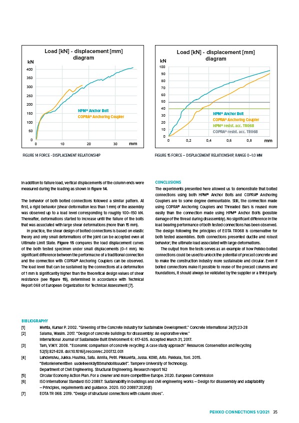
In addition to failure load, vertical displacements of the column ends were
measured during the loading as shown in figure 14.
The behavior of both bolted connections followed a similar pattern. At
first, a rigid behavior (shear deformation less than 1 mm) of the assembly
was observed up to a load level corresponding to roughly 100–150 kN.
Thereafter, deformations started to increase until the failure of the bolts
that was associated with large shear deformations (more than 15 mm).
In practice, the shear design of bolted connections is based on elastic
theory and only small deformations of the joint can be accepted even at
Ultimate Limit State. Figure 15 compares the load displacement curves
of the both tested specimen under small displacements (0–1 mm). No
significant difference between the performacne of a traditional connection
and the connection with COPRA® Anchoring Couplers can be observed.
The load level that can be sustained by the connections at a deformation
of 1 mm is significantly higher than the theoretical design values of shear
resistance (see figure 15), determined in accordance with Technical
Report 068 of European Organization for Technical Assessment 7.
Load kN - displacement mm
kN
100
90
80
70
60
50
40
30
20
10
Load kN - displacement mm
diagram
100
90
80
70
60
50
40
30
20
10
diagram
HPM® Anchor Bolt
COPRA® Anchoring Coupler
HPM® resist. acc. TR068
COPRA® resist. acc. TR068
CONCLUSIONS
The experiments presented here allowed us to demonstrate that bolted
connections using both HPM® Anchor Bolts and COPRA® Anchoring
Couplers are to some degree demountable. Still, the connection made
using COPRA® Anchoring Couplers and Threaded Bars is reused more
easily than the connection made using HPM® Anchor Bolts (possible
damage of the thread during disassembly). No significant difference in the
load bearing performance of both tested connections has been observed.
The design following the principles of EOTA TR068 is conservative for
both tested assemblies. Both connections presented ductile and robust
behavior; the ultimate load associated with large deformations.
The output from the tests serves as an example of how Peikko bolted
connections could be used to unlock the potential of precast concrete and
to make the construction industry more sustainable and circular. Even if
bolted connections make it possible to reuse of the precast columns and
foundations, it should always be validated by the supplier or a third party.
BIBLIOGRAPHY
1 Mehta, Kumar P. 2002. “Greening of the Concrete Industry for Sustainable Development.” Concrete International 24(7):23-28
2 Salama, Wasim. 2017. “Design of concrete buildings for disassembly: An explorative view.”
International Journal of Sustainable Built Environment 6: 617-635. Accepted March 31, 2017.
3 Tam, V.W.Y. 2008. “Economic comparison of concrete recycling: A case study approach” Resources Conservation and Recycling
52(5):821-828. doi:10.1016/j.resconrec.2007.12.001
4 Lahdensivu, Jukka. Huuhka, Satu. Annila, Petri. Pikkuvirta, Jussa. Köliö, Arto. Pakkala, Toni. 2015.
“Betonielementtien uudelleenkäyttömahdollisuudet”. Tampere University of Technology.
Department of Civil Engineering. Structural Engineering. Research report 162
5 Circular Economy Action Plan. For a cleaner and more competitive Europe. 2020. European Commission
6 ISO International Standard ISO 20887: Sustainability in buildings and civil engineering works – Design for disassembly and adaptability
– Principles, requirements and guidance. 2020. ISO 20887:2020(E)
7 EOTA TR 068. 2019. “Design of structural connections with column shoes”.
mm
0
0 0,2 0,4 0,6 0,8
FIGURE 14 FORCE - DISPLACEMENT RELATIONSHIP
400
350
300
250
200
150
100
50
0
0 10 20 30
kN
mm
kN
mm
0
0 0,2 0,4 0,6 0,8
FIGURE 15 FORCE – DISPLACEMENT RELATIONSHIP, RANGE 0–1.0 MM
PEIKKO CONNECTIONS 1/2021 35