FIGURE 2 PRINCIPLES OF A GUSSET PLATE
ARRANGEMENT AS GIVEN IN EUROCODE 1”
Shear connectors are required in the region
of load introduction if the shear strength is
exceeded at the steel concrete interface. The
design shear resistance value is given as 0.40
MPa for rectangular and 0.55 MPa for circular
hollow sections. The resistance values require
that the steel surface in contact with the
concrete is free from oil, loose scale and other
impurities, which might have a negative effect
on the shear action. The shear introduction
length is defined so that it should not exceed
2d of L/3, where d is the minimum transverse
dimension of the hollow section, and L is the
column length.
In the case the shear resistance is exceeded,
Eurocode suggests two types of solutions for
arranging a mechanical shear connection. The
simplest way is to add headed studs in the load
introduction region where the studs may be
designed as with composite beams. The second
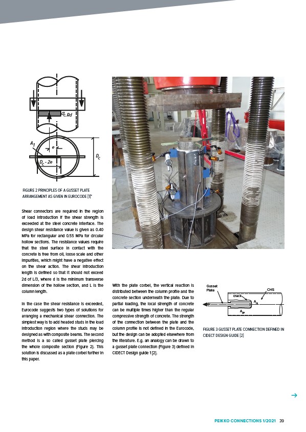
method is a so called gusset plate piercing
the whole composite section (Figure 2). This
solution is discussed as a plate corbel further in
this paper.
Gusset
Plate CHS
crack
Ant
Agv
FIGURE 3 GUSSET PLATE CONNECTION DEFINED IN
CIDECT DESIGN GUIDE 2
With the plate corbel, the vertical reaction is
distributed between the column profile and the
concrete section underneath the plate. Due to
partial loading, the local strength of concrete
can be multiple times higher than the regular
compressive strength of concrete. The strength
of the connection between the plate and the
column profile is not defined in the Eurocode,
but the design can be adopted elsewhere from
the literature. E.g. an analogy can be drawn to
a gusset plate connection (Figure 3) defined in
CIDECT Design guide 1 2.
A1 e
c.Rd
Dc
Dc - 2e
PEIKKO CONNECTIONS 1/2021 39